If you’ve ever worked in electrical testing or power system maintenance, chances are you’ve heard of CT PT analyzers — but have you ever stopped to ask how they actually measure a CT’s secondary current? Let me break this down for you, especially since I’m part of a team that supplies these tools to technicians and engineers every day. CT PT Analyzer
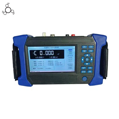
First, let’s get the basics straight: a Current Transformer (CT) is a device that steps down high primary currents (think thousands of amps on power lines) to a manageable secondary current, usually 5A or 1A, that’s safe for meters, relays, and other equipment. When a CT is faulty — maybe it has a shorted turn, damaged insulation, or improper turns ratio — its secondary current won’t be accurate, and that can lead to wrong readings, relay misoperation, or even safety hazards. That’s where a CT PT analyzer comes in; it’s the go-to tool for testing these CTs, and its ability to measure secondary current is one of its core jobs.
Let’s start with how a CT produces secondary current in the first place. When alternating current (AC) flows through the CT’s primary winding, it creates a magnetic field in the core. That magnetic field induces a current in the secondary winding, following Ampère’s law and the turns ratio: I_primary / I_secondary = N_secondary / N_primary. So if you have a 1000:5 CT, 1000A in the primary should translate to 5A in the secondary. But real-world CTs have errors — ratio error, phase displacement, and excitation current — so we need to measure that secondary current accurately to spot those issues.
Now, how does a CT PT analyzer actually do that? It’s not just sticking a multimeter on the secondary terminals and reading a number. That would be too simplistic, and way less precise. Here’s the step-by-step process we use with our analyzers, and what our customers rely on every day.
First, when testing secondary current, the analyzer connects to the CT’s secondary winding — but wait, we don’t do this while the CT is energized from the power system, right? No way, that’s a safety risk. Instead, we use the analyzer’s built-in source to inject a known current into the CT’s primary winding. That’s a key point: most modern CT PT analyzers have a programmable current source that can generate precise AC currents across a wide range, from a few amps up to hundreds of amps, depending on the model. For secondary current measurement, we usually inject a low primary current first, like 5% to 10% of the CT’s rated primary current, to measure the secondary response without overloading anything.
Once the primary current is injected, the analyzer measures the secondary current using a precision current sensing module. Here’s where the tech gets specific: these modules use shunt resistors or current transformers (wait, a CT inside the CT PT analyzer, to measure another CT’s secondary? That’s meta) to detect the tiny voltage drop or magnetic field from the secondary current. Let’s clarify: a shunt-based sensor is just a low-value, high-precision resistor placed in series with the secondary circuit. When the secondary current flows through this resistor, it creates a small voltage (V = I*R) that the analyzer measures with a high-accuracy voltmeter. Since we know the exact resistance of the shunt, we can calculate the secondary current easily. But why not just use a regular current meter? Because regular multimeters aren’t accurate enough for the fine measurements we need — we’re talking about milliamp-level differences here that signal a faulty CT.
The other method some analyzers use is a Hall effect sensor. Hall effect sensors work by placing a semiconductor in the magnetic field generated by the secondary current. The current produces a magnetic field, and the Hall effect creates a proportional voltage output that the analyzer translates back to current. This is great because it’s non-contact — you don’t have to break the secondary circuit to measure, which is faster and reduces the chance of loose connections (a common source of measurement errors in the field). Our team actually finds that Hall effect sensors are more reliable for on-site testing, since they’re less prone to damage from rough field conditions.
But measuring the magnitude of the secondary current is only half the story. A good CT PT analyzer doesn’t just tell you “5A” — it also tells you how that current relates to the primary current you injected, which gives you the turns ratio error. Let’s say we inject 100A into the primary of a 1000:5 CT. The expected secondary current is 0.5A. If the analyzer measures 0.48A, that’s a 4% ratio error — a red flag that the CT is wrong. Also, we measure phase angle: the secondary current should be 180 degrees out of phase with the primary current (that’s how transformers work), but if the CT has a saturated core or a winding fault, that phase shift changes. Our analyzers track that phase difference alongside the current, so you get a full picture of the CT’s health.
Wait, let’s talk about excitation current too — that’s another big one for secondary current measurement. Excitation current is the small current that flows through the CT’s secondary winding when it’s open-circuited (or when we inject primary current) to magnetize the core. A faulty core, like if it’s made of low-grade steel or has damage, will draw more excitation current, which means the secondary current will be less than it should be. To measure this, our CT PT analyzers can perform an excitation test: they open the secondary circuit, apply a known AC voltage across the secondary terminals, and measure the resulting excitation current. This gives us a curve that shows how the CT behaves at different voltage levels, and it’s super useful for spotting core problems that just measuring the secondary current at one point would miss.
I’ve seen so many field technicians get tripped up by this: when they test a CT, they connect their regular clamp meter to the secondary and see a “normal” current, but it’s actually wrong because they didn’t account for the excitation current or phase shift. That’s why a dedicated CT PT analyzer is way better — it’s calibrated to eliminate those errors, and it can measure secondary current with precision down to 0.1% or better. Our team designs our analyzers with that calibration in mind, using industrial-grade components so they hold up in hot, dirty, or remote sites where our customers use them.
Let’s throw in a real example from a customer last month: a maintenance crew at a substation called us because their overcurrent relays were tripping randomly, even under normal load. They tested the CTs with their old multimeter and thought the secondary current was correct (5A at 1000A primary), but when they used our analyzer, we found the secondary current was actually 4.7A — a 6% ratio error. Digging deeper, they found the CT’s secondary winding had a shorted turn, which reduced the number of active turns, so the secondary current was lower, making the relay think the primary current was higher than it actually was. That’s the difference between a basic measurement and a professional analyzer’s secondary current testing — it catches issues you’d miss otherwise.
Now, let’s address a common question: why can’t you use a power quality analyzer instead? Power quality tools measure line currents, but they’re not designed for CT-specific secondary current measurements. CTs have unique characteristics — turns ratio, accuracy class, burden rating — that a general power analyzer doesn’t account for. Our CT PT analyzers are programmed with standard test methods for CTs, like the ones set by IEEE or IEC, so when they measure secondary current, they’re comparing it to the exact standards that utilities use. That’s important because if a CT doesn’t meet IEEE C57.13 standards, it’s not safe for use in critical power systems.
Another thing: when testing secondary current, we have to make sure the burden on the CT is correct. Burden is the load that the secondary circuit places on the CT, like the meters and relays. If the burden is too high, it can increase the secondary current error, even if the CT is good. Our analyzers let you simulate different burden loads while measuring secondary current, so you can test how the CT performs under different real-world conditions. That’s a feature a lot of basic tools don’t have, and it’s one our customers say is a game-changer for their testing.
Let’s wrap up what happens when the analyzer is running through a test. The user connects the analyzer to the CT’s primary (usually via temporary test leads) and secondary terminals. They select the CT’s ratio and accuracy class, choose the test type (ratio, excitation, polarity), and start the test. The analyzer injects a precise primary current, measures the secondary current with its high-sensitivity sensors, calculates the ratio error, phase shift, and excitation current, and displays all the results on a screen — usually with graphs for easy interpretation. Some models even save the test data to a USB drive so you can generate reports for maintenance records, which is a big plus for compliance audits.
I’ve worked with this equipment for years, and the biggest mistake I see new users make is rushing the test. They connect the analyzer, start it, and just look at the secondary current number — but you have to look at the whole picture. Is the phase angle correct? Is the excitation current within limits? Is the burden matching what the CT was designed for? All of these tie back to how the secondary current is measured and what it tells you about the CT’s health. Our team includes support engineers who walk customers through this every time, whether they’re using our entry-level portable analyzers or our bench-top models for lab testing.
If you’re in the market for a CT PT analyzer, remember that not all tools measure secondary current the same way. Look for one with precision current sensing (Hall effect or high-grade shunts), built-in burden simulation, and compliance with industry standards. It’s not just about getting a number — it’s about getting an accurate, reliable measurement that lets you catch problems before they cause downtime or safety issues.

At the end of the day, a CT’s job is to turn high primary current into a safe, predictable secondary current. A good CT PT analyzer’s job is to measure that secondary current accurately enough to tell if the CT is doing its job right. Whether you’re testing CTs at a residential substation or a large industrial power plant, that measurement is the foundation of every CT test. If you’re looking to upgrade your testing equipment or need help picking the right analyzer for your needs, feel free to reach out to our team to discuss your requirements. We’re here to help you get the accurate measurements you need to keep power systems running smoothly.
Partial Discharge Test System References
IEEE Std C57.13-2021, IEEE Standard Requirements for Instrument Transformers
IEC 60044-1:2003, Instrument Transformers – Part 1: Current Transformers
"Current Transformer Testing Principles," Electrical Testing Association, 2022
Wuhan Jiuhua Jingce Power Equipment Co., Ltd.
As one of the most experienced ct pt analyzer manufacturers in China, we offer a wide range of products with superior quality. Please feel free to wholesale bulk durable ct pt analyzer from our factory. For price consultation, contact us.
Address: 601,Unit 1,Building D4-02,Optics Valley Center,303 OpticsValley Avenue,Wuhan
E-mail: market@wuhanjhjc.com
WebSite: https://www.powertransformertester.com/
